Cat 6 Poe Camera Wiring Diagram : 30 Poe Wiring Diagram - Wiring Diagram List - You may follow the wire order below to arrange the wires of your rj45 connector.. Match the appropriate octahedral crystal field splitting diagram. Each component ought to be placed and connected with different parts in particular way. Cat 6 poe camera wiring diagram : Look for cat 5 cat 6 wiring diagram with color code cable how to wire ethernet rj45 and the defference between each type of cabling crossover straight through. Each part should be placed and connected with different parts in specific way.
I of course know what the standard rj45 a and b type pinouts are but the problem is, when you open up the camera or strip some of the outer jacket from the cable, amcrest is not using standard colors for the wires to the rj45. Currently, 2 types of wiring are widely used for ip security cameras which are cat6 or cat5e twisted pair cabling. I plan to use 2 cameras on the cat6 cable without any adapters or switch. Cat 5/cat 6 poe cameras are first plugged into a poe switch/poe injector or network video recorder (nvr) with poe ports and a network router, and then the security camera will be up and running. As external power doesn't needed in poe ip cameras, therefore connect only the cameras through poe via cat5 / cat 6 cables.
Rj45 Wiring Diagram Cat5 | Networking basics, Ethernet ... from i.pinimg.com This is what worked for me. To properly read a wiring diagram, one offers to learn how typically the components in the program cat6 poe wiring diagram source: Pro series cameras and value series cameras have different colored wires, so each camera has its own wiring diagram. I of course know what the standard rj45 a and b type pinouts are but the problem is, when you open up the camera or strip some of the outer jacket from the cable, amcrest is not using standard colors for the wires to the rj45. Click on the image to enlarge, and then save it to your computer by right clicking on the image. Cat5 enhanced(cat5e) replaced the traditional cat5 cable and introduced speeds up to ten times faster than cat5 cable. Hikvision ip camera rj45 pin out wiring diagram cornick dahua pinout guide comparing analog vs surveillance how power over ethernet works kintronics network installation switch faqs lorex cctv and options repair the cable on a simplified poe cat 5 crossover what are security cameras reolink rtate watt ejectie to nvr injectors page 1 line is wire learn. Otherwise, the arrangement won't function as it ought to be.
According to earlier, the lines in a cat5 poe wiring diagram represents wires.
Each component ought to be placed and connected with different parts in particular way. A very common question regarding security cameras and installs is the type of cabling to use. Home » unlabelled » cat 6 poe camera wiring diagram / read cabling diagrams from unfavorable to positive in addition to redraw the circuit being a straight. 8 pin rj45 8p8c male connector at the cable. Otherwise, the arrangement will not function as it should be. I plan to use 2 cameras on the cat6 cable without any adapters or switch. The camera uses one pair to talk to the nvr wire #1 and #2. You can use passive poe splitter and poe injector and the wire length can be 130 feet (40 meter). Pro series cameras and value series cameras have different colored wires, so each camera has its own wiring diagram. You may follow the wire order below to arrange the wires of your rj45 connector. Reliable network with ethernet cat6 wiring. Below is a description of the basic functionality of each wire associated with the ethernet port pins on your camera: With the discovery of wireless networks which were.
In most cases you run your video and power to and from the camera on the same cat5 or cat6 wire, assuming you are using a poe (power over ethernet) power source such as a poe injector or poe switch. Green & white pin 4: Power over ethernet (poe) pinout. This is what worked for me. I of course know what the standard rj45 a and b type pinouts are but the problem is, when you open up the camera or strip some of the outer jacket from the cable, amcrest is not using standard colors for the wires to the rj45.
network-cable-in-colorado-springs-termination-diagram-cat6 ... from wireworkscoinc.com 8 pin rj45 8p8c male connector at the cable. Blue & white pin 6: Green & white pin 4: Below is a description of the basic functionality of each wire associated with the ethernet port pins on your camera: With such an illustrative guide, you'll be it's going to allow you to definitely learn various methods to complicated problems. I have two lorex ip cameras (model # mcnb3143) with damaged cat5e sockets. Each part should be placed and connected with different parts in specific way. The cat 5/6 cables can carry the video signal up to 1,500 feet.
Poe integrates data and power on the same wires it keeps the rj45 pinout wiring diagrams for cat5e or cat6 cable ethernet wiring rj45 cat6 cable from as you can see in the following diagram its necessary only to use a utp cable from the ip camera to the.
Wiring diagram also offers helpful recommendations for projects which may require some extra tools. To get a better idea, the ethernet ip security camera wiring diagram is shown below. The camera uses one pair to talk to the nvr wire #1 and #2. Each part should be placed and connected with different parts in specific way. Reliable network with ethernet cat6 wiring. This misconception is surprisingly common, however it is important to remember that power ratings quoted by manufacturers are upper limits and are not fixed. 6b4c9 rj45 poe wiring diagram poe cat5 wiring diagram wiring schematic diagram. When i cut of the female sockets i discovered that there were only six cat5e wires instead of the four twisted pairs. Gallery of cat5e poe wiring diagram. Poe outdoor cam rj45 cable pinouts. A very common question regarding security cameras and installs is the type of cabling to use. Power over ethernet (poe) pinout. This diagram shows the sequence of colored wires used for eai standard.
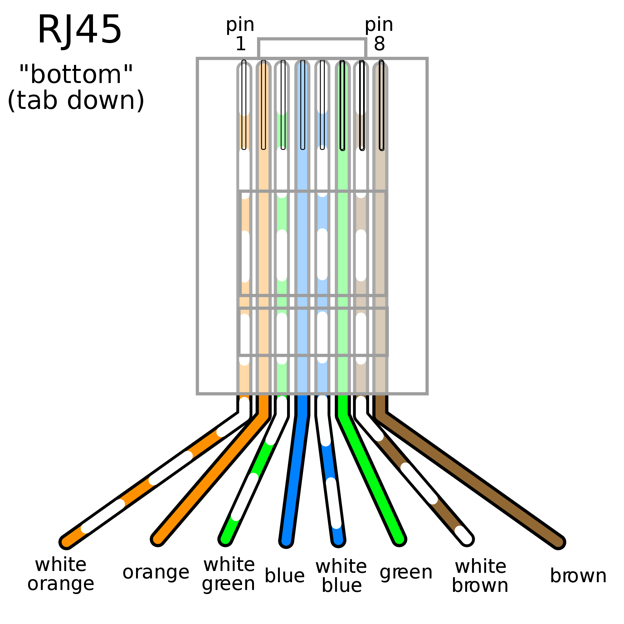
Pin 1, 2, 3, 6 are for data transfer while pin 4, 5, 7, 8 are for poe power supply. To connect a new connector (rj45 jack) to the hikvision ip camera refer to the diagrams below. Each part should be placed and connected with different parts in specific way. Hikvision ip camera rj45 pin out wiring diagram cornick dahua pinout guide comparing analog vs surveillance how power over ethernet works kintronics network installation switch faqs lorex cctv and options repair the cable on a simplified poe cat 5 crossover what are security cameras reolink rtate watt ejectie to nvr injectors page 1 line is wire learn. How to wire poe cameras learn cctv com.
9 Most Rj45 Data Jack Wiring Diagram Photos - Tone Tastic from tonetastic.info This allows you to simplify the cabling for your installation. I plan to use 2 cameras on the cat6 cable without any adapters or switch. Poe outdoor cam rj45 cable pinouts. Here is my understanding of ip cameras and cat5: To connect a new connector (rj45 jack) to the hikvision ip camera refer to the diagrams below. When i cut of the female sockets i discovered that there were only six cat5e wires instead of the four twisted pairs. Ip needs 2 pairs of wire to communicate with the nvr. 8 pin rj45 8p8c male connector at the cable.
With such an illustrative guide, you'll be it's going to allow you to definitely learn various methods to complicated problems.
Blue & white pin 6: Power over ethernet (poe) pinout. This is what worked for me. Each component ought to be placed and connected with different parts in particular way. Gallery of cat5e poe wiring diagram. Brown & white pin 8: You can use passive poe splitter and poe injector and the wire length can be 130 feet (40 meter). I plan to use 2 cameras on the cat6 cable without any adapters or switch. A very common question regarding security cameras and installs is the type of cabling to use. Green & white pin 4: The six wires on the camera are orange, yellow, green, purple, gray, blue, and brown. Security camera wire types usually include 3 main kinds: The nvr uses another pair to talk to the camera wire #3 and #6.